
Free printable
Printable circuit symbols chart
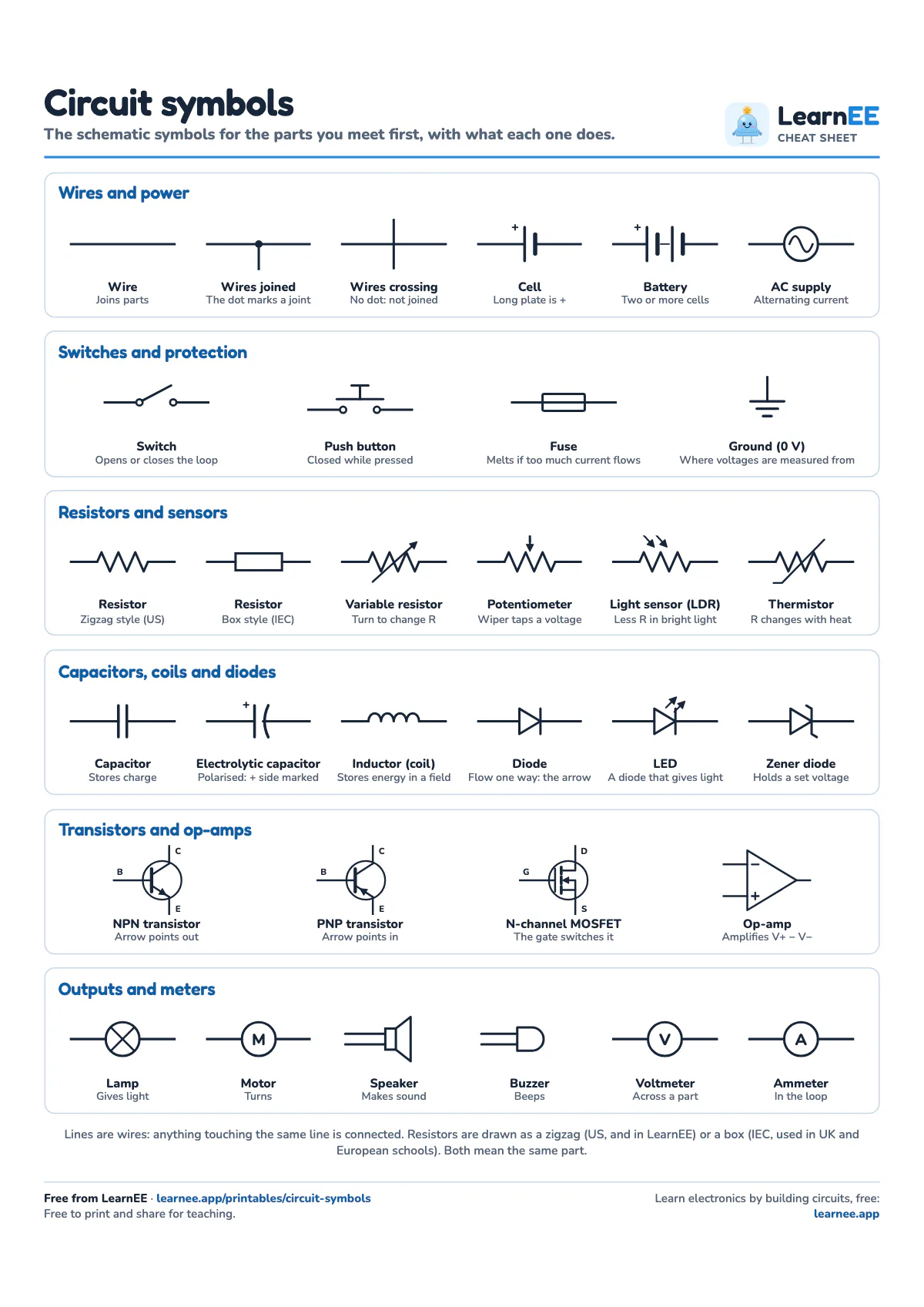
A one-page circuit symbols chart for students reading their first schematics. It shows 32 symbols in six groups, each with its name and a few words on what the part does.
One page. Free to print and share for teaching. Print at actual size (100%), not fit to page. A4 suits most of the world; US Letter suits the USA and Canada.
What's on the sheet
- Wires and power: a wire, wires joined and crossing, cell, battery and AC supply
- Switches and protection: switch, push button, fuse and ground (0 V)
- Resistors and sensors: the zigzag and box resistor, variable resistor, potentiometer, light sensor (LDR) and thermistor
- Capacitors, coils and diodes: capacitor, electrolytic, inductor, diode, LED and Zener diode
- Transistors and op-amps: NPN, PNP, N-channel MOSFET and op-amp, with their pins labelled
- Outputs and meters: lamp, motor, speaker, buzzer, voltmeter and ammeter
How to use it in class
Give it out with a simple schematic, like a battery, switch, resistor and LED, and ask students to name every part and then build it. Later, use it for a quick quiz: cover the names with a strip of paper and see how many symbols students can name. The note at the bottom explains the two resistor styles, so students who learnt the box symbol aren't thrown by the zigzag, or the other way round.
Free lesson
Now build it yourself
Each lesson comes in three short parts: see the idea, try it on a live board, then build it yourself, with quick checks as you go.
“What is electricity?” is lesson 1 of 6 in Copper Flats, Electronics World 1. No account needed: start playing now.
The charts online
The ideas behind it
- What is electricity?Charge on the move: conductors, insulators and why a circuit has to go all the way round.
- Series vs parallel circuitsOne path or many: what stays the same, what adds up, and how to combine resistors.
- How does a diode work?A one-way valve for current: anode, cathode, the 0.7 V forward drop and Schottky diodes.
- Transistor as a switch, explainedA trickle into the base switches a big current: cutoff, saturation and the base resistor.
Questions teachers ask
Why are there two resistor symbols?
Two standards are in use. The zigzag comes from the US (ANSI) standard and is what the LearnEE simulator draws; the plain box is the IEC symbol used in UK, European and Australian schools. They mean exactly the same part.
How do you show that two wires are joined?
With a dot where they meet. Two lines that cross with no dot are not connected. To be safe, many people never draw a four-way joint at all: they offset it into two T-joints, each with its dot.
Which way does the arrow on a diode point?
The way conventional current can flow: from the anode, through the triangle, to the bar, which is the cathode. On a real diode the cathode end has a stripe. An LED is the same symbol with two arrows for the light.
Is the chart free for schools?
Yes. Print it, copy it and share it for teaching. Please keep the footer, which links to the free LearnEE lessons.
More cheat sheets
- Printable resistor colour code chartEvery band colour, how to read 4- and 5-band resistors, and the E12 values with their bands.
- Printable Ohm's law and power cheat sheetThe V = I × R triangle, the power wheel, three worked examples, and units and prefixes.
- Printable electronics formula sheetOhm's law to resonance: the formulas students use most, grouped on one page.
- Printable capacitor code chart3-digit codes, pF to nF to µF, tolerance letters and voltage codes on one page.
- Printable logic gates cheat sheetAll seven gates with symbol, truth table, Boolean expression and chip number.